Path creation tools are applications that allow you to create commonly used geometric paths in a way that is much more efficient than using the Pen tool.
Common geometrical figures (ellipses, rectangles, polygons, etc.) like paths created with the pen tool, are ultimately just anchor points and control handles. However, unlike arbitrary paths, with geometrical figures, the points and control handles follow simple mathematical rules that can be defined by a few parameters, but they must be arranged very precisely. For example, a rectangle must be a closed path of a specific width and height and precisely parallel sides.
The Path Creation tools are simply programs that generate the Anchor Points and Control Handles of geometrical figures based on a few defining parameters, which you specify either graphically or via dialog boxes. These tools are used frequently because:
The simple geometrical shapes that they generate are used very frequently and also appear often in modified form and in combination with one another.
The precise and symmetrical way that the points and control handles must be placed make it hard to draw these shapes with the Pen tool.
There are two broad categories of path creation tools. Those for creating:
When you are using path tools, you are typically creating several (possibly many) objects, and therefore, alignment becomes a critical issue. A typical workflow is to:
Set up a grid or guides to aid in aligning the objects,
Create lines and shapes using the grid or guides to align the objects, and then
Modify, transform, and combine the objects to create an artwork, again using a grid or guides to align the components.
Because, in practice, grids and guides are critical to the typical workflow, we start this page with articles on how to use these alignment aids.
Grids
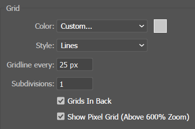
Grid Options Settings
A Grid is a background that looks like graph paper but does not print. You can use a Grid to quickly align objects optically.
To use a Gridin Adobe Illustrator:
To toggle the Grid on or off, execute the View > Show/Hide Grid command.
To tell Illustrator that when moving an object, you want it to snap to the Grid, execute the View > Snap to Grid.
To adjust the Grid settings, execute the Edit > Preferences > Guides & Grid command.
Rulers and Guides
Rulers
How Illustrator Rulers Work
Since the commonest use of Rulers is to place Guides, Ai considers guides a feature of rulers, and to create guides you must first enable Rulers (Ctrl + r).
Using Rulersin Adobe Illustrator:
To toggle Rulers on or off, execute the View > Rulers > Show/Hide Rulers (Ctrl + r) command.
Ai allows you to use Rulers in one of two ways:
Global Ruler. Use a single Global Ruler setting for all artboards, or
Artboard Rulers. Use a different Ruler setting on each Artboard. This is the default. In this mode, Ai will remember where you set the origin point on each Artboard.
To toggle between Global and Artboard rulers, either:
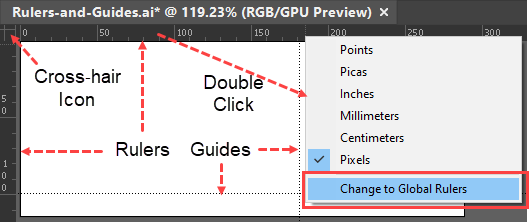
Right-click the ruler. Ai will pop-up a menu that allows you to specify the ruler's measurement units and switch between Global and Artboard rulers , or
View > Rulers > Change to Global/Artboard Rulers.
To set the Ruler's origin (0, 0) point for both the horizontal and vertical rulers:
Go to the cross-hair icon in the upper left corner of the document window where the horizontal and vertical Rulers intersect.
Drag the icon to the Artboard.
Guides
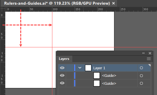
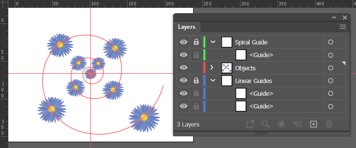
Illustrator Guides appear as Objects in the Layers panel, which you can show, hide, or lock.
Guides are thin, horizontal, or vertical, lines that do not print, and that you can create and place in arbitrary locations to help you position and align objects relative to one another, and to the artboard. You can toggle guides on and off, and you can choose their color and whether the line is solid or dotted
Guides are software objects that are represented in the Layers panel. Consequently, instead of deleting (or clearing) them when they are no longer needed, you can simply make them invisible by clicking the eye icon in the Layers panel. In that way, you can save guides for later use. You can also move a set of related guides to their own layer, name the layer and control the locking and visibility of the entire set as you would any other Layers panel object.
Typically, you create guides using Rulers. However, you can also convert arbitrary lines or objects into guides.
Using Guides
The three basic operations for using standard Guides in Adobe Illustrator are as follows.
Create a Guide:
Ensure that you have Rulers enabled (Ctrl + C)
Place the guide in any of the following ways:
Drag from a Ruler, This will make a guide that is parallel to the Ruler.
Double-click on a Ruler. this will make a guide that is perpendicular to the Ruler.
Shift + drag from a Ruler. This will snap the Guide to the increments on the ruler that is perpendicular to the Guide that you are creating.
To create a vertical and horizontal guideline in one operation, Ctrl + Click + drag the cross-hair icon in the upper left corner of the document window.
Move a Guide:
Make sure that the Guides are unlocked (View > Guides > Unlock Guides).
Get the Selection tool and drag the guide to a new position.
Delete a Guide:
Select the Guide.
Press the Backspace key.
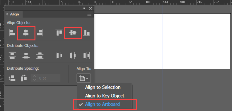
Using Align Panel tools to Center Guides in IllustratorCenter Guides on the Artboard:
Make sure that the guides are unlocked (View > Guides > Unlock Guides).
Select the guides.
In the Align Panel:
Change the Align To option to Align to Artboard.
Vertical Align Center and/or Horizontal Align Center.
Re-lock the Guides.
Convert a Path into a Guide
Converting Paths to Guides in Illustrator
You can make custom guides from any path. This is particularly useful for (A) creating guides from shapes created with the polar or rectangular grid tools, and (B) creating non-linear guides.
To convert any path to a guide in Adobe Illustrator:
Select the lines.
Execute the View > Guides > Make Guides command.
View > Release Guides is the inverse operation. It converts a guide into a line.
Smart Guides
Smart Guides are pop-up guides that appear as you hover over, draw, or transform objects. They provide information that can substantially improve your productivity as you create and layout the elements of your composition. There are seven Smart Guide features, which you can choose to enable or disable. The purpose of this article is to help you get the most out of Smart Guides by describing each of the features in sufficient detail to enable you to (A) know what features are available and (B) to make an informed decision about which features to use.
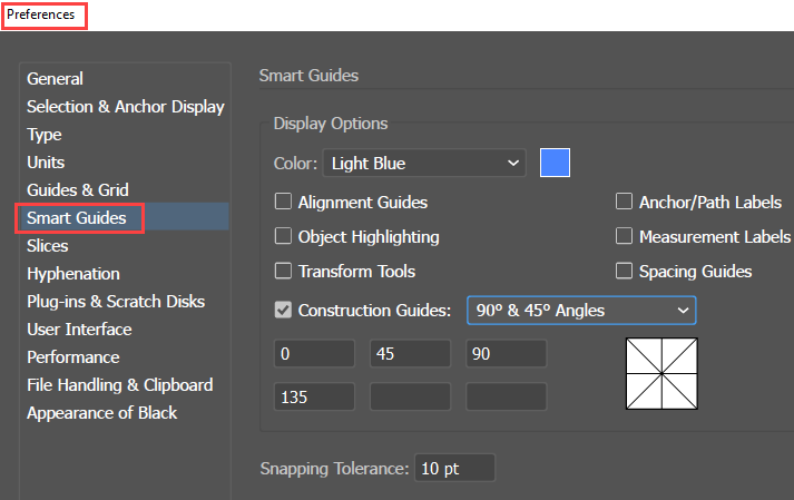
Illustrator Smart Guides Preferences Dialog Box
In the Edit > Preferences > Smart Guides dialog, you can:
Select the color of the guides,
Set the Snapping Tolerance, i.e., how close to an object the cursor must be before Ai launches a Smart Guide feature,
Enable or disable any of the options described below.
Note that turning on View > Snap to Grid or View > Pixel Preview will disable Smart Guides.
Smart Guide Options
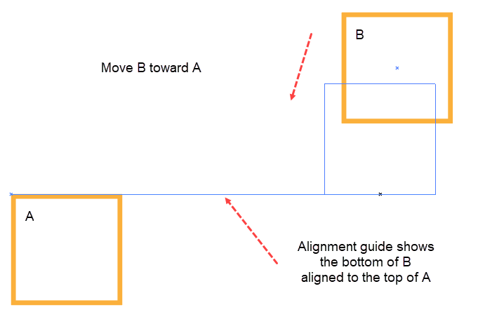
Alignment Guides
Illustrator Alignment Guide
When you are moving an object, alignment guides show you when a feature (e.g., an edge or the center) of the object that you are moving is aligned with a feature of nearby objects. For Alignment Guides to detect the center of a shape, you must have selected the Show Center icon in the Attributes panel.
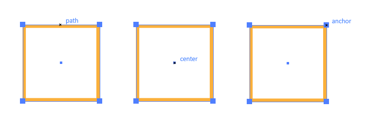
Anchor/Path Labels
Illustrator Smart Guide Anchor/Path Labels
As you move the cursor, Anchor/Path Labels show you when you are hovering over an anchor point or a path segment.
Object Highlighting
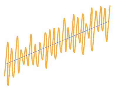
Illustrator Smart Guide Object Highlighting on a path with an Effect
As soon as you hover over an appearance attribute of a path, Object Highlighting shows you the underlying path. This is most useful when the path has an Effect applied to it, as in the figure, where a line's stroke has a scribble effect (Effect > Stylize > Scribble).
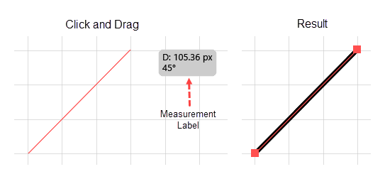
Measurement Labels
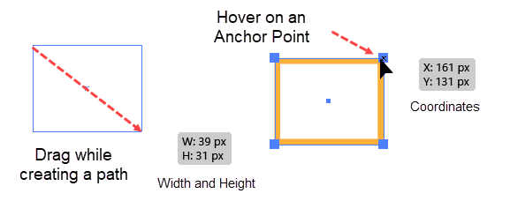
Illustrator Smart Guide Measurement Labels
When you are creating a Live Shape, Measurement Labels will show you the dimensions of the shape. When you hover over an Anchor point of a selected path, Measurement Labels will show you its x-y coordinates. Finally, when you hover over the center of a selected shape, Measurement Labels will show you its x-y coordinates, provided that you have selected the Show Center icon in the Attributes panel.
Transform Tools
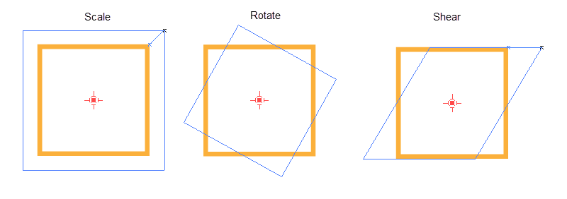
Transform Tool Smart Guides
When you use Transform Tools (Scale, Rotate, or Shear) and you have the Measurement Tools setting enabled in the Smart Guides Preferences panel, the tools will display guides that preview the effect of the transformation.
Spacing Guides
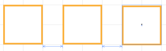
Illustrator Smart Guide Spacing Guides
When you are moving a shape into position with a series of two or more other shapes, Spacing Guides popup to show you when the shape that you are moving has the same relative spacing as the other shapes in the series.
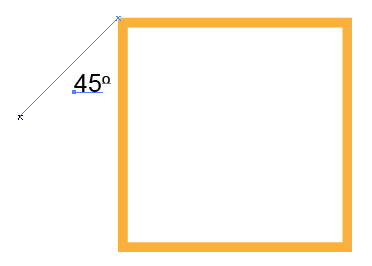
Construction Guides
When you have made the Pen tool or a Live Shape tool active, and you hover its cursor at position that is a specified angle relative to the nearest anchor point of the nearest path, Ai will display a Construction line. You set the angles that trigger the display of Construction Guides in the Edit > Preferences > Smart Guides dialog.
Construction Guide
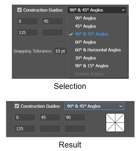
Setting Preferences for the angle of Construction Lines
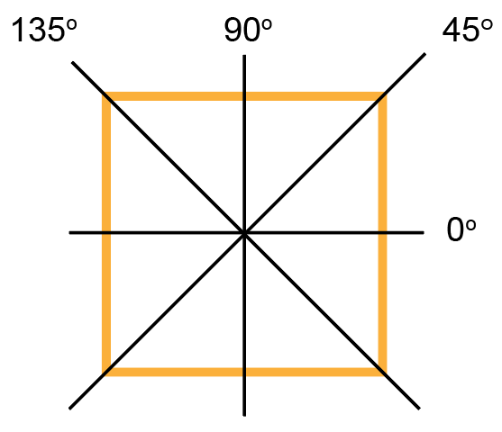
Normal Construction Guide Angle Settings
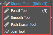
Open Path Tools
Tools for drawing open paths include:
Line Segment
Arc (quarter ellipses)
Curvature tool
Pencil Tool
Line Segment
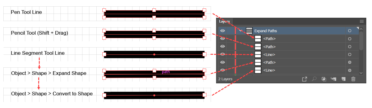
Even though it is not grouped with the other Live Shape tools, the Line Segment tool creates a Live Shape. You can see this in the Layers panel. When you create a straight line with the Pen tool, the Layers panel gives it the default name "Path." But when you create a straight line with the Line Segment tool, the Layers panel will give it the name "Line."
As with most tools you can use the Line tool to create an object either quantitatively or visually.
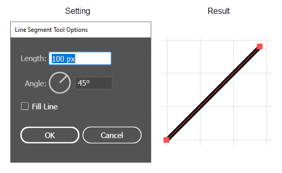
Create a Line Segment Quantitatively
Create a line segment with the Illustrator Line Segment Tool dialog.
To create a line segment using the Line Segment Tool Options dialog box in Adobe Illustrator:
Click once on the Line Segment tool (\) to activate it.
With the tool active, click once on the artboard. Ai will display the Line Segment Tool Options dialog box, which shows the tool's defining properties: Length and Angle.
Assign values to the properties and click OK. Starting from where you clicked, Ai will draw the line that you specified.
When creating a line segment quantitatively , by default Ai uses the stroke color. To tell Ai to use the fill color, click the Fill Line box. However, for that to work, you still must have the stroke color set to none. If you have both a fill and stroke color specified, Ai will use the stroke color, even if you have specified Fill Line.
Draw a Line Segment
Draw a Line Segment with the Illustrator Line Segment tool.
To create a line by drawing with the Line Segment Tool in Adobe Illustrator:
Click once on the Line Segment tool (\) to activate it.
Click and drag on the artboard (Shift + click + drag constrains the drawing angle to multiples of 45 degrees.
Provided that you have turned on View > Smart Guides, as you begin dragging out a line segment, Ai will display a Measurement Label, which shows the segment's length (distance D) and the angle.
When working with the Pen tool, the Smart Guides show only the length of the current line segment. With the Pencil tool Smart Guides do not work at all.
Line Segment Objects versus Straight Line Paths
Live Shape tool lines vs straight-line Paths
The Line Segment tool does not create a simple path as does the Pen tool or the Pencil tool. Rather it creates a line that is a Live Shape. The accompanying figure illustrates the differences. In the Layers panel the Pen tool or the Pencil tool will create a Path; whereas, the Line Segment tool creates a Line. On the art board with Bounding Boxes turned on, Line Segments do not show the bounding boxes, but display only two end points and a center point.
When working with a line that was drawn with the Line segment tool and Bounding Boxes turned on, you can use the Selection (black arrow) tool to move either endpoint of a Line Segment independently, or you can Alt + drag on an endpoint with the Selection tool to rotate the Line Segment about its center. This is not possible with a line that was drawn with the Path tool or the Pencil tool.
Expanding a line (Object > Shape > Expand Shape) turns if from a Live Shape into a regular Path.
Arc Rectangle with Handles Occupying 50% of each Dimension
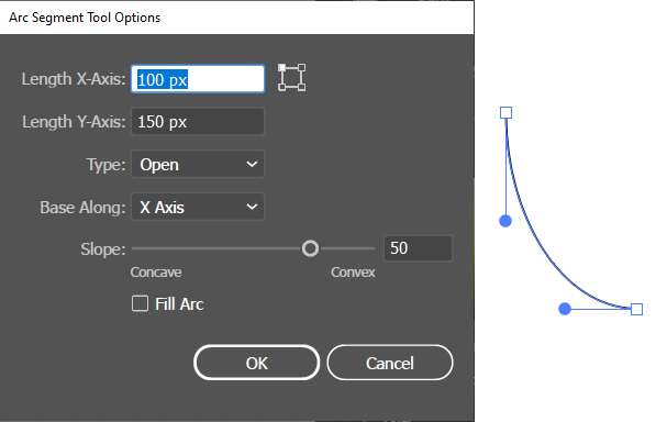
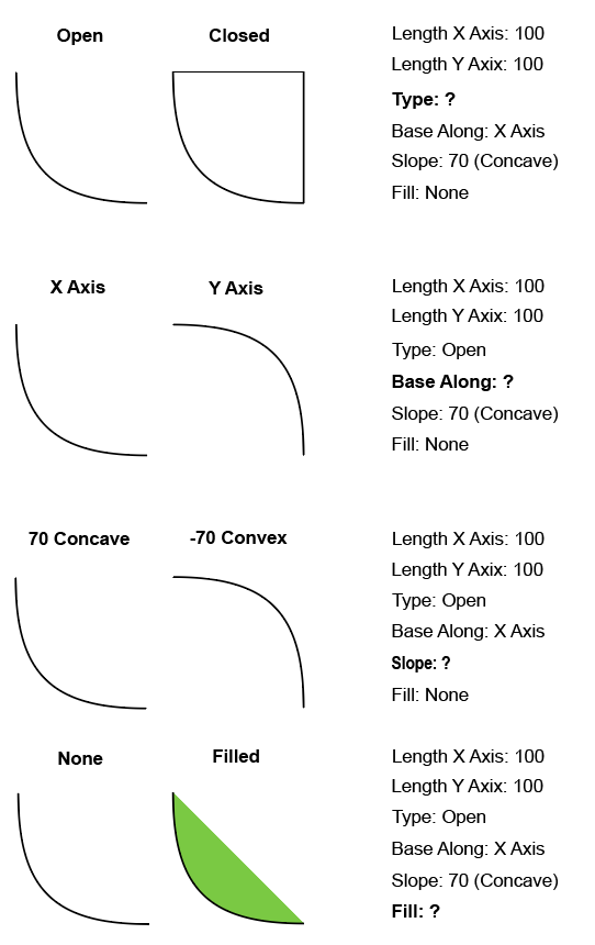
The Arc Tool fills a rectangle with a Bézier curve that arcs from one corner to the other. You set the Length of the rectangle's X and Y axes, in the Arc Segment Tool Options dialog.
The curvature of the arc is determined by perpendicular control handles that extend from the corner where the curve launches to the corner where it lands.
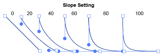
You set the length of the control handles by the Slope setting in the Arc Segment Tool Options box. The Slope is the percentage of the X and Y dimension along which the control handle will stretch.
Slope settings determine the length of the control handles
As with most tools, you can use the Arc tool to create an arc either quantitatively or visually
Create an Arc quantitatively
Arc Tool Options
To generate an arc using the Arc tool dialog box in Adobe Illustrator:
Click once on the Arc tool (\) to activate it.
With the tool active, click once on the artboard. Ai will display the Arc Tool Options dialog box.
Assign values to the options in the Tool Options dialog box. When you press the OK button, Ai will generate an arc from one corner of the box to the other.
Draw an Arc
To draw an arc with the Arc tool in Adobe Illustrator:
Click once on the Line Segment tool to activate it.
Click and drag on the artboard. Think of drawing from one corner of an imaginary rectangle. When you start dragging, Ai will pop up Smart Guide Measurement Labels that tell you how wide and high the imaginary rectangle is. By default, the tool creates a quarter ellipse, with a slope setting that makes each control handle half as long as its dimension.
When working with the tool, you can:
Shift + drag to constrain the path to a quarter circle.
Tap the f-key while dragging to flip the path.
Tap the up and down arrow-keys to change the slope (i.e., the length of the control handles).
Curvature Tool
The Curvature tool (shortcut Ctrl + ~) is an alternative to the Pen tool for quickly creating curves that are made up entirely of Anchor Points that have Control handles (i.e., Smooth Points and Change Direction Points). The tool's distinctive features are that:
To place Smooth Points, it works 3 Anchor Points at a time. When you place a point (say point N), the tool looks back at the previous two points, (N-2, and N-1), and adjusts the launching control handle on point N-2, both handles on point N-1, and the landing control handle on point N so that all three points are connected by a smooth curve. It continues this 3-Point Smoothing process for all subsequent smooth points.
The tool can't get started until you place the third point. so when place the first two points, it simply adjusts the Control Handles so that they are in-line.
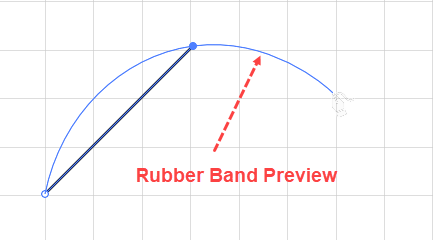
Curvature Tool Rubberband Preview in Illustrator
Once you have placed the first two points, as you move the cursor, to place the third point, the tool displays a Rubber Band Preview that shows you what the curve would look like if you clicked to place an anchor point at that location. Then for all subsequent smooth points, Ai will show the Rubber Band preview.
In contrast to the Pen tool, with the Curvature tool you can, without using special keys or switching to other tools: add, move, delete Anchor Points, create change-direction Points, or adjust Control Handles.
You can use the Curvature tool to easily edit any Path, even if it was not created with the Curvature tool.
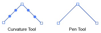
Contrast between a corner made with the Curvature tool and with the Pen tool in Adobe Illustrator. Note that the Curvature tool corner has Control Handles and the Pen Tool corner does not. The Curvature corner is a Change Direction Point, while the Pen tool corner is a true Corner Point.
You can create paths that look like they have straight lines or corner points, but the tool always achieves the look by adjusting Control Handles. What look like corner points (which made with the Pen tool would have no control handles) are with the Curvature tool actually change-direction points with two control handles that are at an angle to one another. Similarly, what looks like a straight line between two corner Anchor Points, will really be two successive Anchor Points with Control Handles that are in-line with one another.
The first Anchor Point is special in that if you close the path by clicking on the starting point (point 1), also becomes the ending point (point N); so the tool must adjust both of its Control Handles to maintain a smooth curve.
The Curvature tool has several drawing modes that may change as you draw. Each drawing mode has a distinctive purpose and in each mode the Curvature tool has distinctive capabilities. Ai displays a modifier icon in addition to the Curvature icon to signal what mode the cursor is in and what you can do when the Curvature tool is in that mode. The cursors, with their mode modifiers are frequently referred to as if they were completely distinct types of Curvature tool cursors. The following table defines all the Curvature tool modes and what the modifiers mean.
Cursor State
Modifier
Means that the tool will:
Start
Start a new path.
Extend
Extend the current active path.
Move Anchor Point
Slide the Anchor Point along the Path or reposition it away from its current location and thereby move the path to a new location.
Add Anchor Point
Insert an Anchor Point into a Path Segment
Close
Click on the Starting Anchor Point of an Open Path and thereby make it a Closed Path. Ai will adjust the control handles not only on the previous Anchor Point but also on the Starting Point.
Activate Path
(Resume)
Reactivate an inactive path so that you can resume editing it.
Alt + click
Place a Change Direction Point. Whenever you click on two successive points with this cursor showing, Ai will connect the two Change Direction points with a straight line, i.e., a segment with both its launching and landing Control Handles in-line with one another so that the segment appears straight.
Create a Smooth Path with the Curvature Tool
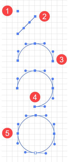
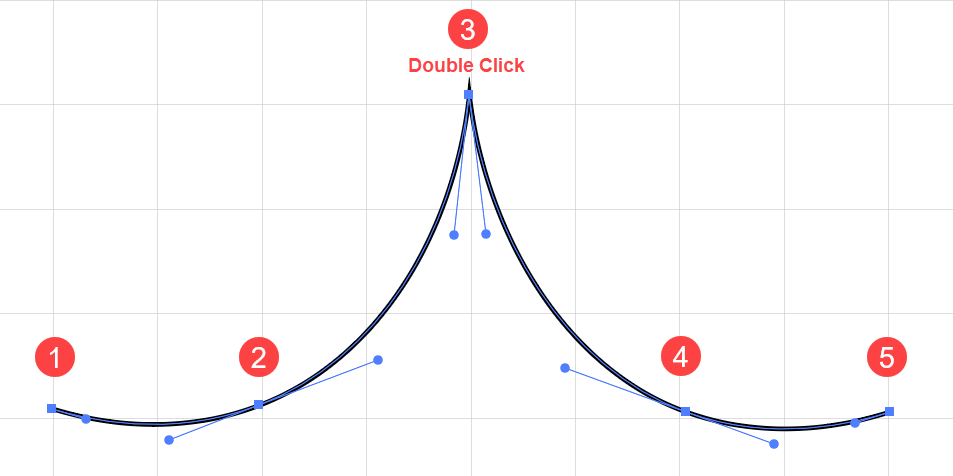
Drawing a Circle with 5 clicks of the Curvature Tool
To use the Curvature tool in Adobe Illustrator:
Assume for the moment that you want to create a path made up entirely of smooth points. The figure illustrates drawing a circle with the Curvature tool with Smart Guides turned on.
Get the Curvature tool.
Click to place the first smooth point. Ai will place a small solid circle to mark the point.
Click again to place a second smooth point. Ai will place a small solid circle to mark the point, switch the first point's marker to be an empty circle, and connect the first and second point with a straight line. But, as soon as you move off the second smooth point, Ai will show a rubber band preview of the curve that would result if you clicked at that point.
Click again to place a third smooth point . Ai will begin its 3-point Smoothing process, and connect the three points with a curve.
Continue until you have placed the last point. If you have closed the path, the Curvature tool will deactivate the path. If you want to close an open path, either press the Escape-key or press the Ctrl-key to get the last used selection tool and click anywhere off the path.
The Shift-key constrains the placement of an Anchor Point so that it will be on a line that makes an angle of 0, 45, 90, 135, 180, 225, or 270 degrees.
Create a Change Direction Point with the Curvature Tool
Change Direction point created by Alt + clicking or double-clicking at point 3, where the tool stops 3-point Smoothing. Since subsequent points continue in the opposite direction, point 3 becomes a cusp point.
To create a Change Direction point with the Curvature tool in Adobe Illustrator:
Get the Curvature tool.
At any point after you create the first two points, instead of simply clicking, Alt + click or double-click to place the Change Direction point. Ai will:
Suspend its 3-point Smoothing process. That is, it will place the landing Control Handle as it normally would, but then begin again as it would from a starting point. In the illustration, this means that it will place the landing control handle at point 3, and then restart 3-point Smoothing.
Create subsequent points as it did from the first point. In the illustration, as you proceed from point 3 to point 4, Initially, Ai will connect points 3 and 4 with a straight line, but as soon as you move off of point 4, Ai will show the Rubber Band preview. Then when you place Point 5, Ai will smooth the path by placing a launching Control Handle at point 3, placing 2 control handles on point 4, and then placing a landing control handle on point 5.
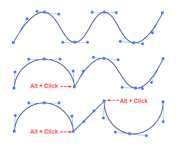
Create a Straight Line with the Curvature Tool
Illustration of 3 comparable Paths: the top one with no Change Direction points, the middle one with 1 Change Direction point, and the bottom one with 2 successive Change Direction points, which creates a straight segment.
To create a straight segment with the Curvature Tool in Adobe Illustrator:
Get the Curvature tool.
At any point after you create the first two points, instead of simply clicking, Alt + click or double-click to place the point.
Then Alt + click or double-click to place the next point. Ai will arrange the two point's Control Handles in line with one another so that the curve will not bend.
Edit a Path with the Curvature Tool
You can perform common path editing operations with the Curvature tool on any Path, even if you did not create the Path with the Curvature tool.
To edit an existing Path with the Curvature tool in Adobe Illustrator:
Get the Curvature tool (Shift + ~).
Hover over an inactive Path that you want to edit, and Ctrl + click on it. Ai will activate the Path so that you can begin editing it. Now, if you hover over an anchor point, Ai will show a Move Anchor Point cursor, which has a modifier symbol that looks like a small circle with a dot at its center. If you hover over a line segment, Ai will show the Add Anchor Point cursor, which has a modifier symbol that looks like a plus sign (+).
With the Path activated, you can do any of the following:
To move an Anchor Point, hover over it until you see the Move Anchor Point cursor, then then click and drag it. You can move the Point along the segment or move it away from the segment. As you move, Ai will automatically adjust the Control Handles on adjacent segments so that the Path remains smooth.
To add an Anchor Point, hover over a Path Segment until you see the Add Anchor Point cursor, and then click to add the point.
To convert a smooth point into a corner point with the Curvature tool, focus on the point and double-click it. Double-clicking a point will toggle it from Change Direction point to a Smooth Point, or vice versa.
To delete an anchor point with the Curvature tool, select it and then press the Delete-key.
The Pencil tool is useful for creating organic (irregular, asymmetric) shapes. It allows you to create a smooth free-form path by making a simple, click + drag gesture. The tool automatically sets down anchor points and can also smooth minor deviations that are introduced by small jerks in the dragging gesture.
The tool's smoothing capability much improves its usefulness but creates a fundamental trade-off: you can have either (A) high accuracy (fidelity to your drawing gesture) and too many anchor points, or (B) nice smooth lines with few anchor points and low fidelity, but you cannot have both. Some segments of the path will always remain either too jagged or else smooth but not accurately placed. For that reason, working with the Pencil tool is an iterative process of drawing and redrawing a path to get it to be both smooth and accurate.
Fortunately, the tool makes redrawing paths easy by allowing you to keep a path selected and correcting it by drawing over it. The Pencil tool has several drawing states, which it signals by adding small icons that modify the cursor. Of these, the states related to redrawing (the Start Path state and the Continue Drawing-Redrawing) are the most important.
Cursor State
Modifier
Means that the tool will:
Start
*
Start a new path
Continue
/
Continue drawing or redrawing the current path. with the pencil tool
Straight Line
_
Shift + drag draw a straight line constrained to 0, 45, or 90 degrees.
Alt + drag draws a straight line that is not constrained to a particular angle.
Close
o
Close a path a path drawn with the Pencil tool.
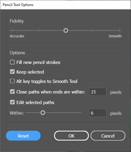
Before you start using the Pencil tool, you will probably want to do some experimentation to find and set the optimal trade-off between fidelity and smoothing. To do that use the Fidelity slider in the Pencil Tool Options dialog.
To set the Pencil Tool Options, double click the Pencil tool, and update the setting.
Note that to use the tool in the normal, iterative (drawing and redrawing workflow), you will want to accept the default Keep Selected option and have the Edit Selected Paths option set to a non-zero value (the default is 6 px). The Edit selected paths option enables or disables the smoothing function of the Pencil. Choosing the Keep selected option makes the smoothing work flow more fluid by keeping whatever path you are working on selected after a drawing gesture so that you can immediately correct problems by retracing the path.
Option
Description
Fidelity
Controls how many anchor-points the Pencil tool will insert for a given gesture. The Accurate setting makes the path faithful to your gesture, but produces the most anchor-points. The Smooth setting produces the fewest anchor-points, but omits small deviations in your drawing gesture.
Fill new pencil strokes
If you have chosen this option, then if you select a fill color before drawing with the Pencil tool, Ai will fill all subsequent Pencil tool paths with the fill that you selected.
Keep Selected
The path will stay selected after you release the mouse button to finish drawing the path.
Alt key toggles to Smooth Tool
Makes pressing the Alt-key invoke the Smooth Tool instead of drawing an unconstrained straight line.
Close paths when ends are within:
Set a value for how close you must get to the starting point before Ai will close the path.
Edit selected paths Within: _ pixels
Set a value for how close you must get to a path before a gesture counts as retracing and correcting the path trajectory.
Drawing with the Pencil Tool
Because of the imperfections of freehand drawing, working with the Pencil tool is an inherently iterative process of drawing and corrective redrawing. Fortunately, with the default Edit selected paths option selected in the Pencil Tool Options dialog, you can refine a path by simply drawing over it with the Pencil tool. There is no separate editing process; just draw over imperfections until they look the way you want.
To draw a free-hand path in Adobe Illustrator:
Single click the Pencil tool.
Draw the first approximation of the path with your mouse or stylus.
If you want to redraw any part of the path, place the Pencil tool close to the path and draw over it to smooth or reposition it. For the redrawing gesture to be successful, the tool should be at least as close to the path as specified in the Edit Selected Paths slider in the Pencil Tool Options panel.
Hints
Adding Straight Lines with the Pencil Tool. To use the Pencil Tool to draw a straight-line segment (either by itself or as a continuation of a free-form path): Alt + click and drag. When you Alt + click, the cursor will display the Straight-Line cursor modifier. When you release the mouse button, the tool will draw the line.
To use the Pencil Tool to draw a straight-line segment constrained to a 45-degree or 90-degree angle either by itself or as a continuation of a free-form path: Shift + click and drag.
Further Smoothing a Free-form Path. The Smooth tool is an alternative to using the Pencil tool's iterative (Keep Selected and Edit Selected Path) workflow to reduce the number of anchor points in a path. However, the Smooth tool works on any path.
To smooth a path with the Smooth tool:
Double click the tool to invoke the Smooth Tool Option dialog and set the Fidelity slider.
Select the target path.
Get the Smooth tool and trace over the selected path.
Pencil Tool and Related Open Path Tools
Erasing Part of a Free-form Path. In contrast to the Eraser tool, which cuts a swath the size of its brush into any object, the Path Eraser tool is designed specifically to erase parts of a path by using a tracing gesture.
To precisely erase parts of a path:
Select the path.
Get the Path Eraser tool.
Trace over the part of the selected path that you want to erase.
Optionally, reconnect the paths with the Pencil tool.
Join Two Paths with the Pencil Tool. To join two parts of a path or to rejoin two parts of a path after you have created a gap by an erasure.
Select both paths.
Hover on an endpoint until you see the tool enter the Continue state cursor (/).
Get the Pencil tool and draw the connection.
Closed Path Tools
Live Shapes and Their Defining Properties
Tools for drawing closed paths include:
Live Shape Tools
Rectangle
Rounded Rectangle
Ellipse
Polygon
Star
Blob Brush Tool
Live Shape Tools
Orientation
Live Shape tools programmatically generate all of the anchor points and control handles needed to create common geometric shapes from a few properties that define the shape. You can supply the defining parameters, quantitatively via a dialog box or visually via gestures of a mouse (or a tablet stylus).
Using these tools not only provides a faster way to create basic shapes, but Illustrator has largely eliminated the need for using tools other than the Transformation panel to move, scale, rotate, reflect, or shear Live Shapes.
Creating a Shape
The operation of all Live Shape tools is similar, so let the following example stand for them all.
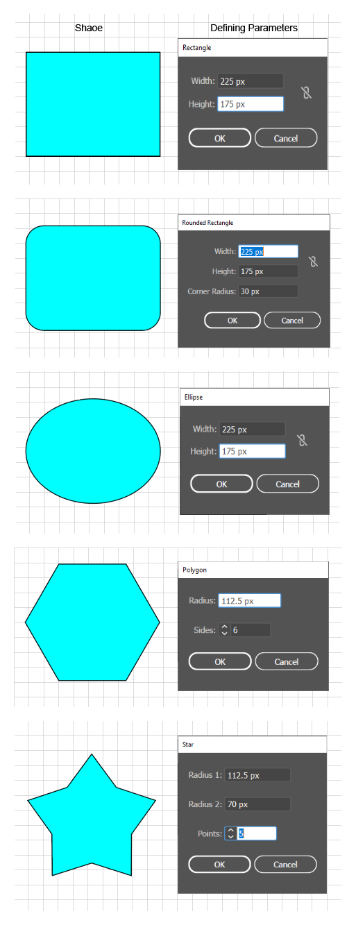
Generating a Live Shape Quantitatively
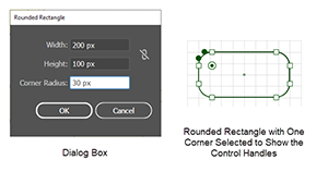
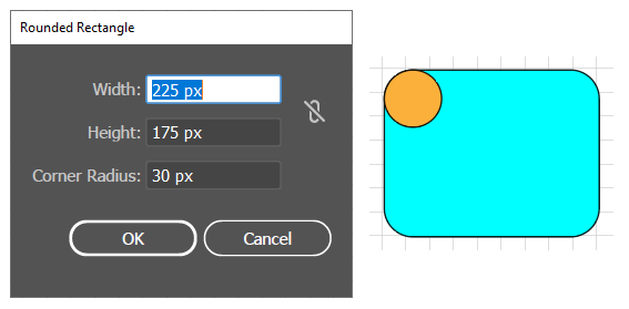
Create a Live Shape with the Rounded Rectangle dialog.
Suppose that you want to generate a rounded rectangle using the quantitative method of supplying the parameters in a dialog box. You would simply click the Rounded Rectangle tool, then click on the artboard (which makes Ai pop up the dialog box. Then you enter the three defining properties of a rounded rectangle: height, width, and the radius of the corners. From the three parameters Ai, will generate 8 smooth anchor points and 8 control handles placed at exactly to correct locations to create a perfectly symmetrical rounded rectangle, a process that would be slower and more difficult to do accurately with the Pen tool.
Drawing a Live Shape Visually
If you want to work visually, you simply click the Rounded Rectangle tool (Ai changes the cursor to a cross hair) and instead of clicking on the artboard, you click and drag diagonally with the mouse. As you drag, Ai uses your mouse coordinates to deduce the defining properties and then sends them to the shape tool's program, which will place the control points and render the shape.
While drawing a Rectangle, Rounded Rectangle, or an Ellipse (i.e., when the cross-hair cursor is active), the following modifier keys are helpful:
Shift + drag to constrain the shape to be symmetrical (e.g. square or circular).
Alt + drag to draw from the center.
Spacebar + drag to move the shape while drawing.
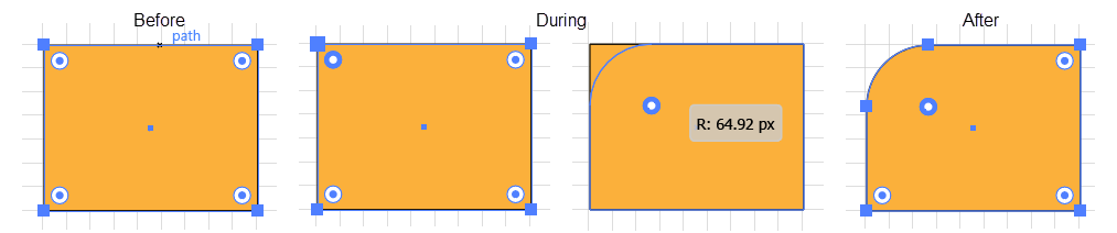
Adjusting a Shape
In a typical workflow, you want to make some adjustments to a newly created shape before considering it final. For example, if you have just created a rounded rectangle, you might decide that the corners are too big, or that two of the corners should be chamfered or that its center should be aligned with the edge of another element. You can make any of these common adjustments either quantitatively or visually.
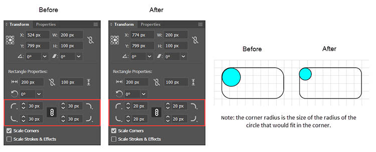
Quantitatively Adjusting a Shape with the Transformation panel
You can quickly adjust Live Shapes quantitatively via the Transform panel dialog (Window > Transform), which provides a form that includes fields showing the current values of all the properties that are applicable to the currently selected Live Shape. When you change a property value, the shape will change immediately to reflect the new setting.
The accompanying example illustrates using the Transformation dialog, to alter the corner radius.
Adjusting a Live Shape with Transformation Panel
Visually Adjusting a Shape
Provided that you have enabled Bounding Boxes (View > Show Bounding Box) and Corner Widgets (View > Show Corner Widget), you can use these features (see below) to visually adjust the shape's width, height, and corner radius.
In addition, as of Illustrator CC 2015, Live Shapes provide on-art, Live Control Widgets. You can select a tool for a particular shape and use the tool's on-art widgets to adjust special features. Furthermore, you can use the Bounding Box, Corner Widgets and on art control widgets without leaving the tool that you used to create the shape.
Difference between Live Shapes and Closed Paths
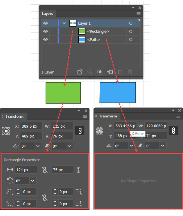
Difference between Live Shapes and regular Closed Paths illustrated in the Transform panel.
Live shapes differ from a closed path created with the Pen tool in the following ways:
Live Shapes have corner widgets that are displayed by default. With generic paths (open or closed) corner widgets are not available until you select the corner with the Direct Selection tool.
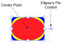
Live Shapes may have distinctive on-art, Live Control Widgets, while generic paths do not:
Rectangles and Rounded Rectangles, in addition to corner widgets, have a center point with which you can move the shape.
Polygons, in addition to corner widgets, have a widget that allows you to adjust the number-of-sides.
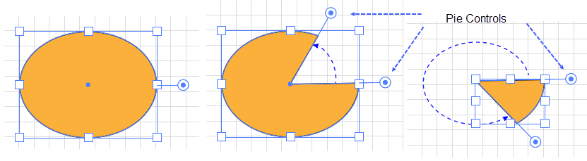
Ellipses have a pie widget, which allows you to remove a pie shaped slice from the ellipse or reduce the ellipse to a single slice.
Lines have end widgets that allow you to change the orientation by dragging one end while the other remains fixed, and they have a center point and a rotation widget, that allows you to rotate the line about its center point.
In the Layers panel, when you create a Live shape, it will have the name of the shape tool that you used to create it. For example, if you create a rectangle with the Rectangle tool, the Layers panel will give it the default label <rectangle>; whereas, if you create a generic path with the Pen tool, the Layers panel will give it the default label <path>.
The Transformation panel nicely exhibits the properties that distinguish a Live Shape (e.g., created with the Rectangle tool) from a shape with the same structure created with the Pen tool.
Converting Shapes to Paths and Paths to Shapes
To convert a Live Shape to a path and vice versa:
Object > Shape > Expand Shape turns a Live Shape into a regular shape.
Object > Shape > Convert to Shape turns a regular shape into a Live Shape.
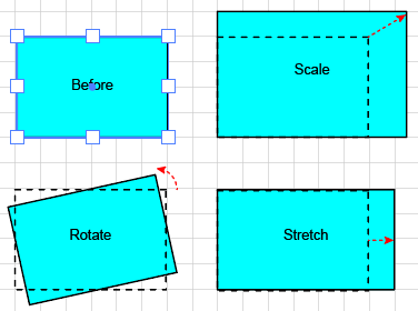
Bounding Box Transformations
Bounding Box Transformations
By default, whenever you select one or more objects Ai displays a Bounding Box surrounding the selection. Since when you create a shape it is selected, unless you have Bounding Boxes disabled, you will see a newly created shape surrounded by a Bounding Box. Bounding Boxes allow you to quickly transform an object visually by dragging handles.
To transform objects with a Bounding Box in Adobe Illustrator:
Ensure that View > Show Bounding Box (Ctrl + Shift + b) is toggled on.
Select the objects.
Do one of the following to transform the selection:
Scale selected objects proportionately, by either: (A) dragging a corner anchor point, or (B) Shift + dragging any anchor point.
Rotate selected objects by moving the cursor to a corner until Ai displays a curved double arrow cursor and drag to rotate the selection.
Stretch selected objects in one dimension by dragging a side anchor point.
To use the Corner Widgets or the on-art Live Controls (such as the Polygons widget for increasing the number of sides), you must have Bounding Boxes enabled (View > Show Bounding Box, Ctrl + Shift + b).
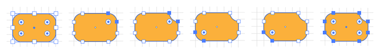
Corners
Rectangles, stars, and polygons have Live Corner Widgets. You can change the style or the radius of a corner; and you may do so quantitatively or visually.
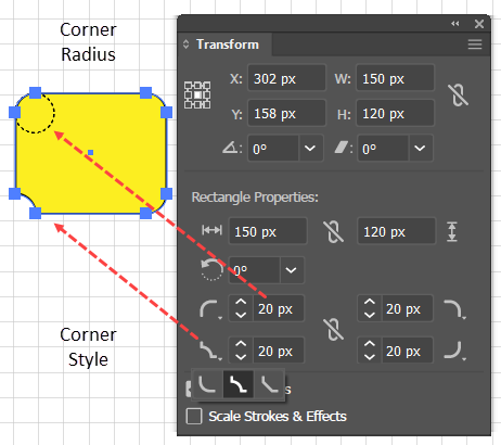
Modify a Corner Quantitatively
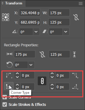
Use the Transformation Panel to Change a Corner's Style or Radius
To change the style or radius of a corner quantitatively in Adobe Illustrator:
Select the shape.
Get the Window > Transform panel.
In the panel's Rectangle Properties section, update the Corner Type and/or Corner Radius values of the corners that you want to change.
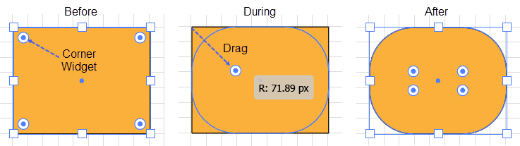
Visually Modify a Corner-Widget
Simultaneously change the curvature of all corner widgets using the Direct Selection tool.
To visually change the style or radius of one or more corners in Adobe Illustrator, you must be aware of two things:
To work with Corner Widgets, you must ensure that the View > Show/Hide Bounding Box toggle is set to Show Bounding Boxes and that the View > Show/Hide Corner Widgets toggle is set to Show Corner Widgets.
With Live Shapes, you can use either Selection tool, but with arbitrary paths, you must use the Direct Selection tool. For paths that you draw with the Pen tool the corner widgets may not show up until you select the path with the Direct Selection tool. For that reason, the following instructions specify using the Direct Selection tool.
To simultaneously change the radius of curvature of all the shape's corners,
With the Direct Selection (white arrow) tool click, on the shape, but do not click on any individual corners. Ai will display the corner widgets.
With the shape selected, click + drag any one of the corners. As you drag the widget away from the corner, toward the interior of the shape, Ai will increase the corners' radius of curvature.
To visually change the radius of one or more corners:
Change the curvature of only selected Corner Widgets using the Direct Selection tool.
Direct Select (white arrow) the corner that you want to modify.
Drag the selected Corner Widget.
To visually change the corner style:
For each corner that you want to modify, Direct Select (white arrow) the entire corner, including the anchor points and the widget.
Alt + Click repeatedly to rotate through the styles.
Change the Style of a Corner Widget with the Direct Selection tool.
Rectangle, Rounded Rectangle, and Ellipse Tools
How Rectangles, Rounded Rectangles, and Ellipses are Related
These three tools are related in the following ways:
They are defined by width and height parameters (whereas polygons and stars are defined by radius parameters).
By default, they are drawn from the top left corner (whereas polygons and stars are drawn from the center). And, since the Rectangle, Rounded Rectangle, and Ellipse tool are defined by width and height, they can be easily nested in one another.
They have a center point, by which you can drag them with the Shape or Selection tools to reposition them.
Rectangle Tool
You can create a rectangle either quantitatively via a dialog box or visually by mouse gestures.
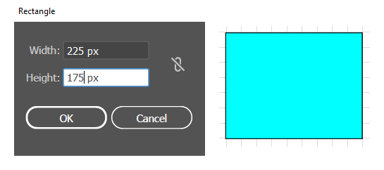
Generate a Rectangle Quantitatively
Create a Rectangle with exact dimensions using the Rectangle dialog.
To create a Live Rectangle with precise dimensions via a dialog box: in Adobe Illustrator:
Click the Rectangle tool. The cursor will change to a cross-hair.
Click once on the artboard. Ai will display the dialog box.
Update the fields and click OK.
Set Corner Widgets' curvature and style using the Transformation Panel.
Note that you can enter arithmetic expressions in the dialog box fields. For example, to make a rectangle that is half the size of the one in the accompanying figure, you could enter 225/2 and 175/2.
To adjust the type of corner, click the icon next to the corner radius field in the Properties > Transformation panel.
Note that rectangles that you create with the Rectangle Tool are basically the same as rounded rectangles that you create with the Rounded Rectangle tool. Both have bounding boxes and corner widgets, but in Live Rectangles, the corner radius is set to 0.
Drawing a Rectangle Visually
To draw a rectangle visually with the Rectangle tool in Adobe Illustrator:
Click the Rectangle tool. The cursor will change to a cross-hair.
Drag the cross hair diagonally to begin drawing a rectangle of the desired size.
Use any of the following modifier-keys to adjust the creation process:
Shift + drag the cross-hair cursor to constrain the rectangle to a square.
Alt + drag the cross-hair cursor to draw the rectangle from the center.
Spacebar + drag the cross-hair cursor to move the rectangle while drawing.
Release the mouse button. Ai will switch to the (black arrow) Selection tool.
Optionally, adjust the rectangle. Ensure that you have enabled Bounding Boxes (View > Show Bounding Box) and Corner Widgets (View > Show Corner Widget) and do any of the following:
Adjust the dimensions or rotation with the bounding box features.
To round all the corners, drag any corner widget.
To round a single corner, Select it (with the black arrow). Ai will darken the selected widget. Then drag the control widget.
To round several corners, Shift + Select them (with the black arrow). Ai will darken the selected widgets. Then drag a selected control widget.
To visually change the style of a rounded corner (among Round, Inverted Round, and Chamfer), repeatedly Alt + click any corner with the Selection tool. To change just selected corners, select them first, and then Alt + click.
Move the ellipse by positioning the cursor over the center point and dragging.
Rounded Rectangle Tool
You can create a Rounded Rectagle either quantitatively via a dialog box or visually using mouse gestures.
Generate a Rounded Rectangle Quantitatively
Create a Rounded Rectangle with exact dimensions using the Rectangle dialog.
To create a Live Rounded Rectangle with precise dimensions via a dialog box: in Adobe Illustrator:
Click the Rounded Rectangle tool. The cursor will change to a cross-hair.
Click once on the artboard. Ai will display the dialog box.
Update the fields and click OK.
Note that you can enter arithmetic expressions in the dialog box fields. For example, to make a rounded rectangle that is half the size of the one in the accompanying figure, you could enter 225/2 and 175/2.
To adjust the type of corner, click the arrow next to the corner icon in the Window > Transformation panel
Draw a Rounded Rectangle Visually
To draw a Live Rounded Rectangle visually with the Rounded Rectangle tool: in Adobe Illustrator:
Click the Rounded Rectangle tool. The cursor will change to a cross-hair.
Drag the cross hair diagonally to start drawing an ellipse of the desired size.
Use any of the following modifier-keys to adjust the creation process:
Shift + drag the cross-hair cursor to constrain the rounded rectangle to a square.
Alt + drag the cross-hair cursor to draw the rectangle from the center.
Spacebar + drag the cross-hair. cursor to move the rectangle while drawing.
Release the mouse button. Ai will switch to the Selection tool.
Optionally, adjust the rectangle:
Ensure that you have enabled Bounding Boxes (View > Show Bounding Box) and Corner Widgets (View > Show Corner Widget).
Adjust the dimensions or rotation with the bounding box features.
To change the radius of all 4 of the corners, drag any corner widget.
To change the radius of a single corner, select the corner (with the black arrow). Ai will darken the selected widget. Then drag the control widget.
To change the radius of several corners, Shift + Select the corners (with the black arrow) . Ai will darken the selected widgets. Then drag any selected widget.
To visually change the style of a rounded corner (among Round, Inverted Round, and Chamfer), repeatedly Alt + click any corner with the Selection tool. To change just selected corners, select them first, and then Alt + click.
Move the rounded rectangle by positioning the cursor over the center point and dragging.
Ellipse Tool
You can create a Live Ellipse either quantitatively via a dialog box or visually by mouse gestures.
Generate an Ellipse Quantitatively
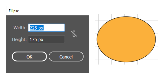
Create an Ellipse with exact dimensions using the Ellipse dialog.
To create a Live Ellipse with precise dimensions via a dialog in Adobe Illustrator:
Click the Ellipse tool. The cursor will change to a cross-hair.
Click once on the artboard. Ai will display the Ellipse dialog box.
Update the fields and click OK.
Note that you can enter arithmetic expressions in the dialog box fields. For example, to make an ellipse that is half the size of the one in the accompanying figure, you could enter 225/2 and 175/2.
Draw an Ellipse Visually
Draw an Ellipse with the Ellipse tool.
To draw an Ellipse visually with the Ellipse tool in Adobe Illustrator:
Click the Ellipse tool. The cursor will change to a cross-hair.
Drag the cross hair diagonally to start drawing an ellipse of the desired size.
Use any of the following modifier-keys to adjust the creation process:
Shift + drag the cross-hair cursor to constrain the ellipse to a circle.
Alt + drag the cross-hair cursor to draw the ellipse from the center.
Spacebar + drag the cross-hair cursor to move the ellipse while drawing.
Release the mouse button. Ai will switch to the Selection tool.
Optionally, adjust the ellipse:
Ensure that you have enabled Bounding Boxes (View > Show Bounding Box) and Corner Widgets (View > Show Corner Widget).
Adjust the dimensions or rotation with the bounding box features.
Move the ellipse by positioning the cursor over the center point and dragging.
Use the Pie Control to create an ellipse with a missing slice or with a wedge as shown in the accompanying figure above.
Polygon and Star Tools
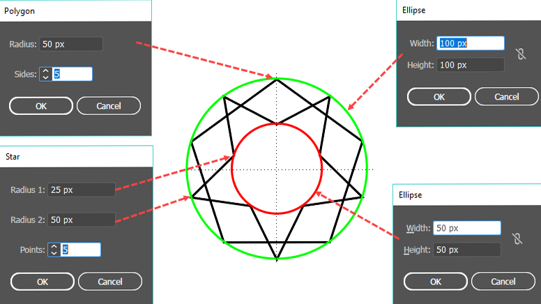
How the box-oriented Ellipse and the radius-oriented Polygon and Star tools are related.
Unlike Rectangles, Rounded Rectangles, and Ellipses, which are box-oriented (i.e., their size is defined quantitatively by the width and height of a box that contains the shape), the Polygon or Star are radius-oriented. That is, the Polygon is defined by the radius of the circle that contains the shape and the Star is defined by the radius that contains the interior points and the radius that contains the exterior points. Furthermore, when drawing with these radius-oriented tools, you draw not from corner-to-corner of a containing box, but from the center of the shape to the circumference of a circle that contains the entire shape.
The accompanying figure graphic shows the relationships among the radii that define the polygon and star in their respective dialogs and the width and height parameters that define circles generated with the Ellipse dialog.
Polygon Tool
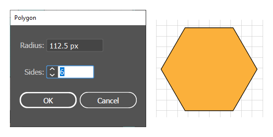
Create an Polygon with exact dimensions using the Polygon dialog.
You can create a Polygon either quantitatively, via a dialog box, or visually by using mouse gestures.
Generate a Polygon Quantitatively
To create a Live Polygon with precise dimensions via a dialog boxin Adobe Illustrator:
Click the Polygon tool. The cursor will change to a cross-hair.
Click once on the artboard. Ai will display the dialog box.
Update the fields and click OK.
Note that you can enter arithmetic expressions in the dialog box fields. For example, to make a polygon that is as wide as an ellipse like the one in the above (Draw an Ellipse) figure that is 225 pixels wide, you would have to have a polygon that has a radius that is half that size. Instead of entering 112.5, you could just enter 225/2 and get the result shown in the accompanying figure.
Draw a Polygon Visually
To draw a polygon visually with the Polygon tool in Adobe Illustrator:
Click the Polygon tool. The cursor will change to a cross-hair.
Position the cursor where you want the center of the Polygon to be. Drag the cross hair to draw a polygon from the center outward:
While dragging, use any of the following modifier-keys to modify the creation process:
Shift + drag to constrain the Polygon while drawing so that it rests on a side (rather than on a corner).
Spacebar + drag to move the Polygon while drawing.
Click the Up and down arrow keys to increase or decrease the number of sides.
Release the mouse button.
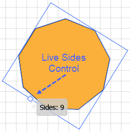
You can adjust a finished polygon in any of the following ways:
Change the number of sides when drawing with the Polygon Tool.
To move the Polygon, position the cursor over the center point, click and drag.
To increase or decrease the number of sides, drag the Live Control.
To round all the corners of a Polygon:
Click the polygon with the Direct Selection tool.
Drag the Corner Widget. Ai will round all the corners.
To change the style or rounding of the individual corners of a polygon, first with the Direct Selection tool (Ctrl + click) select the individual corner Anchor Points (not the Corner Widgets) that you want to change. Alternatively, to select all the corners at once, click the Polygon once with the Direct Selection tool. Ai will highlight the Anchor Points and show the Corner Widgets. Then:
To round the selected corners and control the radius of curvature, simply drag the Corner Widget of one of the selected corners.
To visually change the style of all the selected corners, Alt + click the Corner Widget of any one of the selected corners. With each click, Ai will rotate among the options (Round, Inverted Round, and Chamfer).
Star Tool
You can create a Star either quantitatively, via a dialog box, or visually by using mouse gestures.
Generate a Star Quantitatively
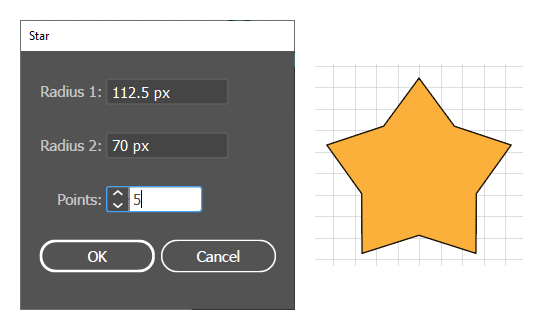
Create an Star with exact dimensions using the Star dialog.
To create a Star with precise dimensions via a dialog boxin Adobe Illustrator:
Click the Star tool. The cursor will change to a cross-hair.
Click once on the artboard. Ai will display the dialog box.
Update both radius fields and the number of Points field and click OK.
Note that you can enter arithmetic expressions in the dialog box fields. For example, to make a star that is half as wide as an ellipse that is 225 pixels wide, you would have to have a polygon that has a radius that is half that size. Instead of entering 112.5, you could just enter 225/2 and get the result shown in the accompanying figure.
Draw a Star Visually
To draw a Star visually with the Star tool in Adobe Illustrator:
Click the Star tool. The cursor will change to a cross-hair.
Position the cursor where you want to center of the Star to be. Drag the cross hair to draw a Star from the center outward:
Use any of the following modifier-keys to adjust the Star during the creation process:
Shift + drag to constrain the star to be upright.
Spacebar + drag to move a star while drawing it.
Use the Up and down arrow keys to increase or decrease the number of points on the Star.
Ctrl + drag inward or outward to decrease or increase the acuteness of the Star's points.
Alt + drag to constrain the Star to look like an American flag Star or a Star of David. That is. configure the Star so that the segments on either side of each point are aligned.
To modify a Star's corners, first with the Direct Selection tool, Ctrl + click to select the corners that you want to change. Alternatively, to select all the corners at once, click the Star once (but not on a corner) with the Direct Selection tool. Then:
To round a selected corner and control the radius of curvature, simply drag the Corner Widget of one of the selected corners.
To change the style of all the selected corners, Alt + click the Corner Widget of one of the selected corners. With each click, Ai will rotate among the options (Round, Inverted Round, and Chamfer).
The Blob Brush tool paints a Closed Path with a Fill Color.
Blob Brush Tool
Overview
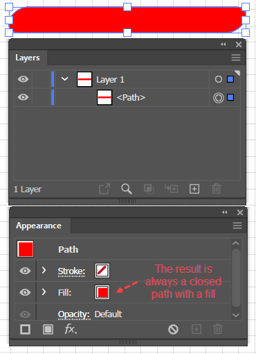
Clicking and dragging with the Blob Brush tool creates, not a line, but a closed path that is filled with the stroke color that was in effect when you started drawing. For example, suppose that in the Appearance panel you set no fill but a red stroke, and then you click and drag freehand horizontally with the mouse. Ai will draw an automatically smoothed, closed path with a red fill that is as high as the default width of the tool's brush and as long as the length that you dragged the cursor. Illustrator calls this object a Blob.
When you are drawing with the Blob Brush tool and have both a stroke and a fill defined, you will draw with the stroke color, i.e., the stroke color takes precedence over the fill color. However, if you deselect and reselect the object, the Appearance panel will show that you have created a closed path with a fill.
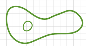
Drawing a Compound Path with the Blob Brush Tool
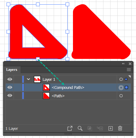
You can also enhance a blob by creating another overlapping blob. Ai will automatically merge the blobs (provided that you draw with the same color). Furthermore, the tool's default behavior is that you do not even need to select the old paths before you merge blobs. The result is a more complex closed path. But, if you switch colors or create a blob, that does not overlay another blob of the same color, Ai will assume that you want to start creating an entirely new blob.
You can also create a Compound Shape (a shape with a hole in it) using the Blob Brush. In the accompanying figure, the path on the right part of the figure is a clone of the one on the left, except that it has been painted in, thus eliminating the hole, and thereby creating a simple closed path.
Blob Brush Tool Options
You can adjust the degree of smoothing as well as the shape, size, and orientation of the tool's brush via the Blob Brush Tool Options dialog box. To open it, double-click the Blob Brush tool (which is grouped with the Brush tool; or alternatively, if the tool is already selected, press the Enter key.
Ai's default, behavior is that when you draw a new shape with the Blob Brush tool that overlaps an existing blob of the same color, Ai merges the new blob with the original blob, even if the original blob was not selected. You can change this default behavior by checking the Merge Only with Selection option checkbox, which tells Ai that if you erase or add new strokes, they should only affect the selected object. If you choose this option, you will probably want to also check the Keep Selected checkbox (in the upper left of the dialog box), which tells Ai that after creating or extending a blob, it should remain selected.
Note that any calligraphic brush works like a Blob Brush.
Use the Blob Brush Tool
To use the Blob Brush in Adobe Illustrator:
Get the Blob Brush tool, which is grouped with the Brush tool.
"Paint" a Blob by clicking and dragging with the mouse or stylus. Ai will create a closed path with a fill.
Continue to "paint" with the same color to add new, overlapping closed paths to a previously created closed path.
Hints:
Draw slowly, so that the tool's automatic smoothing feature has maximum effect.
Use the eraser tool and the smooth tool to clean up the drawing.
Use the square brackets keys to dynamically decrease ("[") or increase ("]") the size of the brush.
Shift + drag to constrain the drawing direction to 0, 45, or 90 degrees.
Use the Eraser tool to remove unwanted parts of a shape. However, the Eraser tool does not have a Fidelity (Smoothness) setting; so, you have to use the Smooth tool to clean up after using the Eraser tool.
To erase part of a blob:
Select the part that you want to erase.
"Paint" with the Eraser tool over the part that you want to erase.